Trace Route is a useful tool that is used to determine the path taken by packets when going to a certain IP Address.
If you have multiple paths to a certain address and you want to know what exact path is taken, this is the tool for you.
But how does it work exactly? Let’s take a look.
Time To Live (TTL)
In order to prevent routing loops on a network (where packets may be continuously forwarded between loops non stop), TTL was introduced.
A packet is assigned a specific Time To Live (TTL) value, once this value is depleted the packet will be dropped. Think of it literally as how long the packet has ‘to live’, a sort of morbid countdown if you will.
But what causes the TTL value to be decremented?
Every time a packets passes through a ‘hop’ on the network, its TTL value is decreased by one.
As mentioned, when a packet has a TTL value of 1 and then passes over to the next hop device, the device essentially drops the packet and sends a reply to the original sender saying that the packet was dropped.
How Trace Route Uses TTL to its Advantage
Trace Route utilises ping packets with varying amounts of TTL values….what does that mean in plain English?
Let’s break it down. Consider the below network:

Let’s say we want to see the exact route that our laptop on 10.10.10.10 takes to contact 10.10.10.20. As we can see from our topology, the packets will either travel via R2 or R3.
For the first hop, the device you are using Trace Route from sets the TTL of the ping packet to 1.
This means it will inevitably die after the first hop…on purpose!
When it gets dropped as a result, the device we are on will get a reply from that hop device saying that it had to drop the packet.
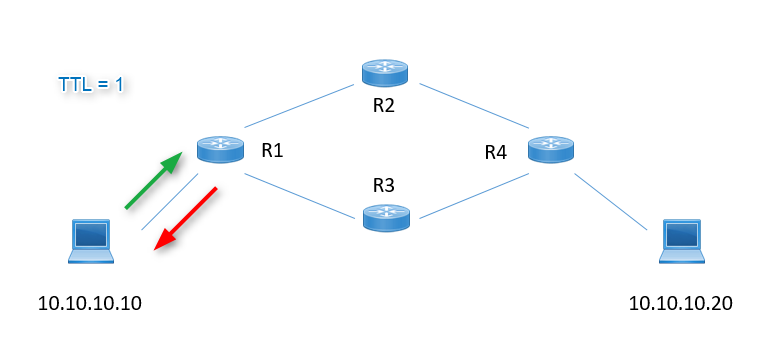
From this reply, we know the first hop.
Our device will then send another packet but this time with a TTL of 2, this will go through the first hop (and have its TTL value decremented to become 1). It will then be dropped at by the device used as the second hop, with that device sending a reply to us saying that it dropped the packet.

Just like before, we now know the second hop thanks to the reply we receive.
This continues for as much as is needed to find the entire route.
In our example, the process is repeated for the next further hop, and the TTL is set to… you guessed it! 3!

Last but not least, we will reach our intended device at 10.10.10.20. This would be confirmed with a final push using a TTL of 4:
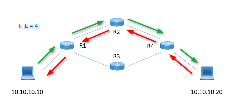
Now we have reached out destination and seen the route taken along the way. We should now also have an understanding of what TTL is, and how it is used to determine the path a packets travels using Trace Route.